The base panel, the cover panel and the heating coil are delivered individually packaged. The standard module length is 2.5 m, so the components can be easily installed one by one. The additional components (please order separately) are enclosed in separate packaging.

Adjust and cut the basic wall panel to wall size with a mitre saw. If the baseboard is laid around corners, it can be mitred to the exact angle with the mitre saw. For 90° angles, the mitre pieces included in the scope of delivery can also be used (if taken into account in the order). The wall should be equipped with the baseboard heating strip over the entire width so that the wall is also heated in the corners and the area classically susceptible to damp is eliminated.
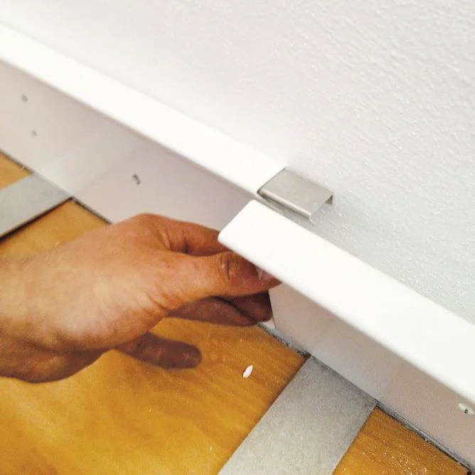
Connect the wall panels with the butt connectors and place all wall panels in the room - also in the corners - then align them.

The holes (Ø 8.5 mm) in the base cover at 50 cm intervals serve as a drilling template. Use a drill with 8 mm diameter. Then insert 8 mm dowels with collars and fasten the fascia with 6 x 50 mm screws.

After fixing the base fascia to the walls, the next step is to attach the plastic brackets. The holes can also be drilled directly through the fascia with a 6 mm drill. Then 6 mm dowels are to be placed and the plastic holders are to be fastened with screws measuring 4 x 40 mm. The pre-drilled holes are at a distance of 50 cm. A distance of at least 15 cm should be maintained to the end of the wall (wall termination).

Align the heating registers. Remove the copper fins at the places where the plastic brackets are to sit later. Four fins per clip are removed. To do this, remove the fins from the heating tubes from the side with a (needle-nose) pliers using a twisting motion. Caution: The fins are very sharp-edged. We recommend wearing work gloves. Only remove as many fins as necessary, otherwise the heating power will be unnecessarily reduced.
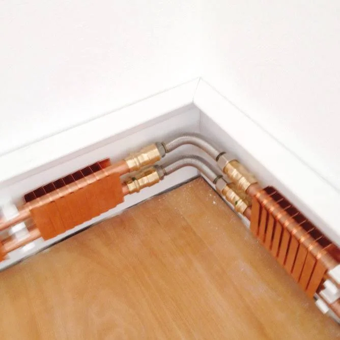
Hook the pipe registers into the plastic brackets. Important: Install the fin pack so that the larger fin duct is fixed on the wall side. Conventional soldering or press fittings for copper pipe can be used for the connection.
IMPORTANT
First connect and then place in the clips. If necessary, these can be taken down again for connecting to further registers.
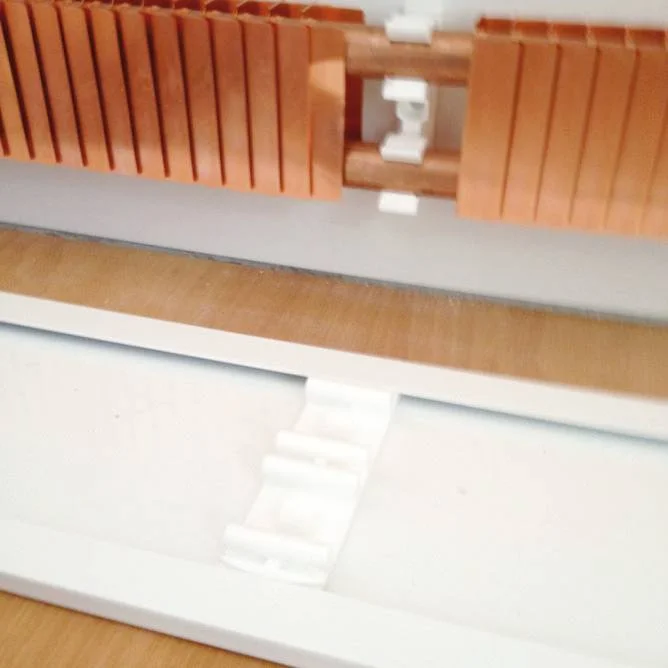
For lengths > 8 m, compensators must be installed between two heating coils. If there are no possibilities for length expansion, e.g. in the case of wall projections or connections to the supply line, a compensator must also be installed in a corner from a coil length of 3 m onwards.
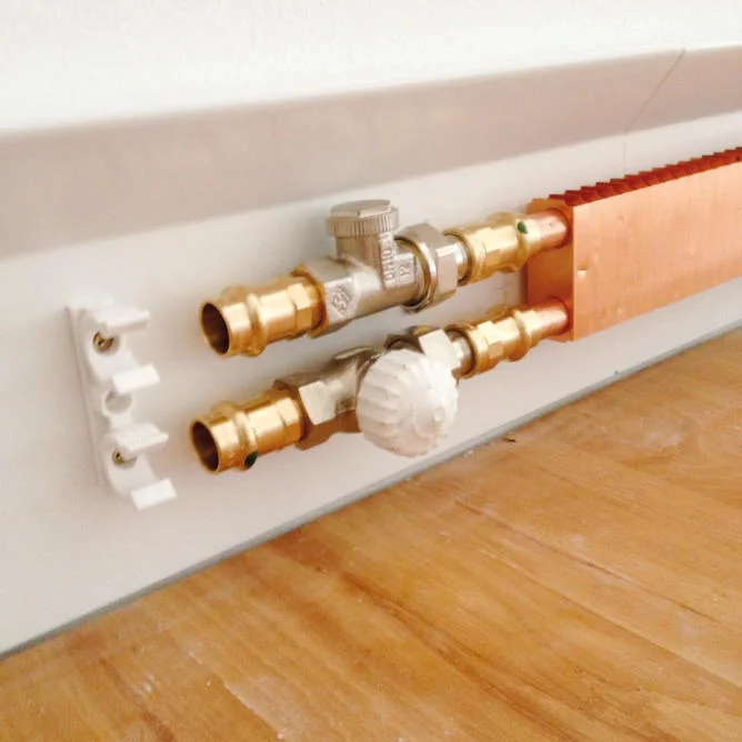
The counterparts (clip upper part) of the plastic holders are now installed in the cover panel. To do this, place the clip upper part lengthwise in the cover panel and then turn it 90° into the holding position and align it. The cover panels are connected to each other using the butt connectors for the cover panel. Then place the cover trims accurately on the plastic holders and snap them into place with hand pressure.
End pieces (supplied in pairs, left and right version) for lateral covering of the pipe registers are inserted with the tab into the grooves of the cover panel. For better hold, bend the tabs at the outer edges (red arrow) slightly in opposite directions so that they are locked in the groove.
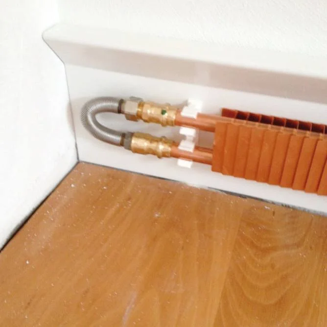
The baseboard can be connected via distribution systems, e.g. as with underfloor heating, or via a thermostatic valve directly on the baseboard. In the latter case, an opening must be provided in the cover panel for the thermostatic valve.
For screw connections, make sure that the front surface/front side of the screw connection is vertical and thus parallel to the cover panel. Flush-mounted connection with an individual room controller is also possible. Combinations with valve radiators are also possible. The maximum length of a heating circuit is 12.5 m for the ECH-3 system and 7.5 m for the ECHL-3D system. The flow must be connected to the lower copper pipe.
The connection between the lower and upper pipes of a heating coil can be made both with a deflection compensator and with elbows. With the help of a t-piece, it is also possible to install a vent if there is no other possibility of venting. If a vent or a thermostatic valve is installed, it should be ensured that the cover can be removed again later. If necessary (e.g. if furniture does not allow free access), the cover panel must be divided (offcuts can be used here) to create an inspection opening.
The installation of a skirting board heating system is extremely simple, which also makes it easy to assemble and install in older or even listed buildings. It is not necessary to chisel open walls or lay water pipes or cables. Baseboard heaters from Energy-com can be integrated into almost any room quickly and in a space-saving manner without extensive conversion measures and can be used both in new buildings and in Old building renovation. The entire construction is mounted on the entire wall by means of a powder-coated and aluminium basic wall panel and covered by a cover panel. It makes no difference whether you choose a water-bearing baseboard or a electric skirting board heating, because the base cover, cover cover and heating register make up the main structure of your skirting board heating in both variants. You can install this yourself in just a few steps. The additional components such as plastic brackets, end pieces and butt connectors are part of the typical accessories that you must also order.
While the water-bearing models, similar to underfloor heating, are connected to the water circuit by means of a distribution system or via a thermostatic valve, the electric baseboard heating is connected to the power supply. Select the wattage that suits your individual needs, which can be between 125 and 575 watts for the electric baseboard heaters and between 88 watts and 420 watts for the water-guided models. We will be happy to assist you in selecting the appropriate wattage. The electric baseboard heater is connected to the TS radio room thermostat via a wireless radio control using a switch socket, allowing you to set and regulate the desired room temperature.
The heating elements are each supplied in a length of 2.5 m and can be cut to any wall size with the help of a mitre saw, so that a simple assembly is always guaranteed, which fits perfectly to your spatial conditions. Mitre pieces from our accessories catalogue help when laying around corners at precise angles.
The connections are to be made with commercially available solder or press fittings. The standard colour is "pure white" (RAL 0916). However, for a visually matching room design, the trims can be supplied in any RAL colour as desired. In this way, both the water-bearing version and the electric heating strip can be perfectly matched to the room appearance. For a continuous baseboard length of more than 15 m, an expansion compensator must be used between the copper pipes for the water-bearing baseboards. The expansion compensator is included in our delivery programme.
You will find detailed information on the installation of baseboard heating strips including helpful pictures in our installation instructions!